INSTALLATION INSTRUCTIONS FOR 944/968 FRONT CONTROL ARM
Congratulations!!! You have made an excellent choice in the purchase of your A-Arm from Racer’s Edge. Please take the time to review these installation instructions as it is important that the work is carried out as described. It is recommended that these parts be installed by a professional and the directions be read in their entirety more than once until thoroughly understood before work begins.
The design of the pin used in the Racer’s Edge A-arm addresses the issue of failed pins which occur in the factory A-arm pin design. This new design gives the joint extra strength and even allows the use of longer pins at the outer pickup to correct the geometry of cars which have been lowered from stock ride height. Proper installation of these A-arm pins however requires that the spindle be drilled oversize and tapped with a 0.750” 16 TPI tap.
Ideally, the spindles should be brought to a machine shop where the spindles can be fixtured appropriately. The factory bore in the spindle which accepts the factory pin is 17mm in diameter. This bore must be “indicated in” precisely to make sure that the new bore will be centred and true to the existing bore. This is VERY IMPORTANT as the new pin must be perfectly perpendicular to the bottom spindle surface so the pin spacer sleeve will sit flush against the spindle.
Drilling the spindle bore: The spindle pin bore is approximately .84” long. Ideally you want the first .40” (as the pin enters the bottom of the bore) to be bored to .750” and the remainder of the bore to be tapped to accept a .750” by 16 TPI bolt. This process is a minimum 3 step process. First, after the spindle has been indicated in true to the existing bore, it must drilled using an 11/16” bit as this is the dimension needed for a ¾” 16 TPI tap. Second, the first .40” of the bore must be counter bored to .750”. Third, the remaining 11/16” bore must be tapped to .750” 16 TPI. This basically sets up the bore so that there is a .750” bore to the centre of the pinch bolt hole, and beyond that, it is tapped at ¾” 16 TPI.
Installing Arm in Chassis: Once your spindle is bored and tapped you may proceed with reassembling your front suspension. Install the pin into the spindle bore and screw it in until the relief groove in the pin lines up with the pinch bolt bore in the spindle so you can install the 10mm pinch bolt. Torque the 10mm pinch bolt to the factory spec of 37 ft-lb.
If the A-arm is not yet connected to the chassis you will need to do this now. The arm is installed so the tabs that stick off of the front of the arms are on the lower part of the arm and the retaining circlip for the outer bearing is down. Install the front and rear mounts and torque all bolts to the original factory specs. Now, slide the pin spacer sleeve over the pin so that the larger diameter face sits against the bottom of the spindle and the smaller face is pointing down. Note (All of the machined parts and bearings that are provided are a very close tolerance fit. Do not force any assemblies together. Usually if you spend a little more time lining things up with very light pressure, the assemblies will slide together.) Now, take the arm and rotate it up into position and guide the pin through the large outer bearing bore. Next install the 12-point nut on the bottom of the pin and torque the 12 point nut to 150 ft-lb.
Last Checks: This completes the installation of the A-arm. The 2nd page of these instructions provide some pictures to more clearly illustrate what things should look like when assembled. It would be advisable to recheck and re-torque all the fasteners which were loosened during this installation process. It is also required to have the front end aligned.
NOTE: As with any highly stressed part, a periodic inspection should be performed on your arms in order to assure they are in proper working order.
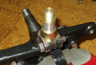
The picture above shows the pin in the arm with the spacer slipped over the pin. It clearly illustrates that the spacer is installed with the small end of the spacer in contact with the bearing. It also illustrates that the spacer is installed so that it sits above the arm, and the 12-point nut, which is barely visible at the bottom of the pin, is recessed in the bearing housing lower cup. DO NOT install the arm upside down as this would position the spacer incorrectly in the “cup” and binding would occur. It must look as it does in the picture above when assembled.
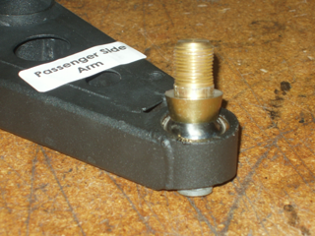
This picture shows another view of the pin with spacer as it is with reference to the spindle. The picture shows the spacer's larger diameter side in contact with the spindle. The pin should be screwed into the spindle until the pinch bolt can be easily engaged. When the pinch bolt can be easily slid into position, the nut on the pinch bolt should be installed and torqued to 37 ft-lb. After this pinch bolt is installed and torqued, then you can install the spacer and slide the arm over the pin. Torquing the 12-point nut to 100 ft-lb is the last step in the process. Do not use any lubricant on the nut. If the arm needs to be removed for any reason, remove the 12-point nut first. Do not try and remove the pinch bolt from the bottom of the spindle while the 12-point nut is still in place.